Division Tab
Division Tab
The Division Tab is used to divide the cabinet into boxes, and to apply doors, drawers and shelves as desired.
- On the preview of the cabinet, click on the box that is to be divided.
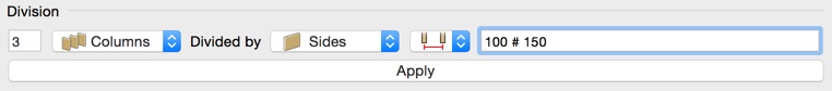
- Enter the number of divisions required and choose if you want to create columns or boxes (vertical divisions, or horizontal divisions).
- Choose the divider type (Shelves, Stretchers, Sides, Styles).
Select how the distribution should be done. You can choose between: „Centers“, „Inside“, „Front“ and „Front (+Inside)”. If you don't want to distribute equally you can enter the measurements for the distribution in the text field. With the options "Front" and " Front (+Inside)" it is possible to construct fronts of the same size with optionally the same clear dimensions of the distribution.
- Fill in the proportions to determine how the cabinet should be divided. # is used as a wildcard. For example, If you fill in 100 # 150, the first segment (from the bottom or left) has a measure of 100, the last one has a measure of 150. The unused space is allocated to the middle division. If there were two or more wildcards, the unused spaced is divided by the number of wildcards. Alternatively, you can split into proportions or percentages (e.g. 3:2:1 or 40% 25% #).
- Press Apply to check your divisions in the preview.
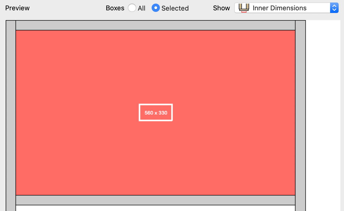
Just below the division, you can preview the dimensions, either just for the selected or for all boxes:
The number and measurements of columns and boxes can be changed at anytime:
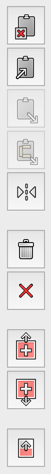
With the toolbar on the left of the preview, you can perform the following actions (from top to bottom):
|
Copy the division to clipboard. Paste the division from the clipboard. Paste the flipped devision from clipboard. Flip the division of the selected box. Delete the division from a box.
Create new box before the selected box.
|
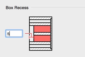
Box Recess
All sub-boxes of a selected box can be set back by a certain value (negative values are possible too, which will cause the feature to extend towards the front of the cabinet).
Front Details: Constructing drawers, doors, flaps and blind fronts
For each box you can choose an overlay or inset front. In the case of doors, this also applies to further divided boxes. In the preview, doors, flaps and lifting flaps are marked with a triangle in the direction of opening. Drawers are marked with a cross, blind fronts with a double cross and folding flaps with a central line.
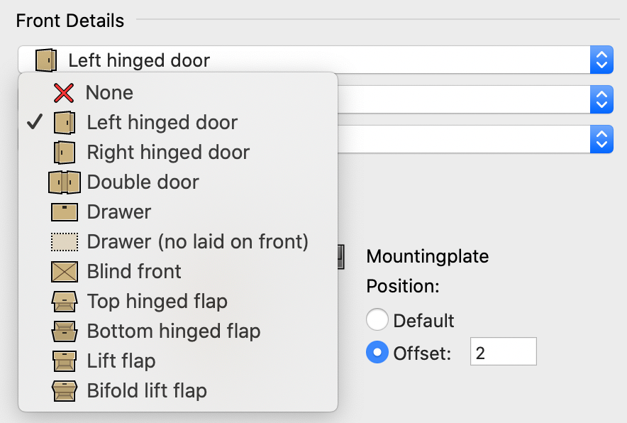
As an additional front detail, you can customize the surface of doors, drawers and flaps. Select whether the surface is to be created "Plain" or as a "Frame".
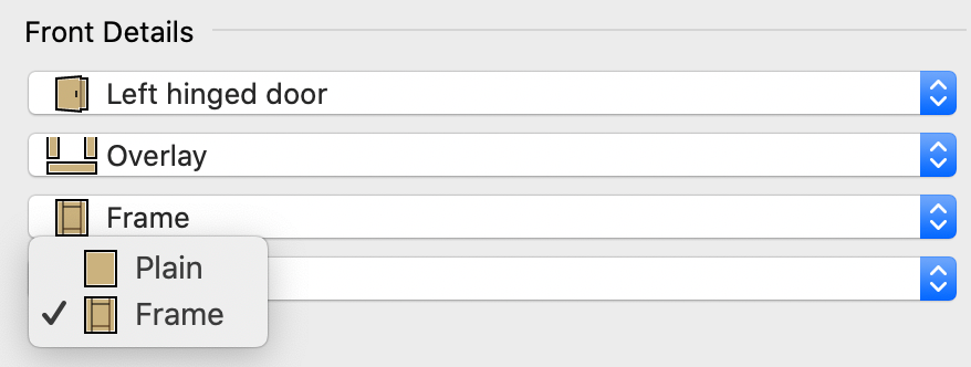
By selecting "Frame", a frame front can be configured for the carcase furniture 3D.
Edit frame front
You can choose between the following options during configuration:
- "Custom": An already stored frame configuration
- "Edit": Create a new frame configuration
If you select "Edit", the new window "Edit Frame..." opens. The following configuration options are possible:
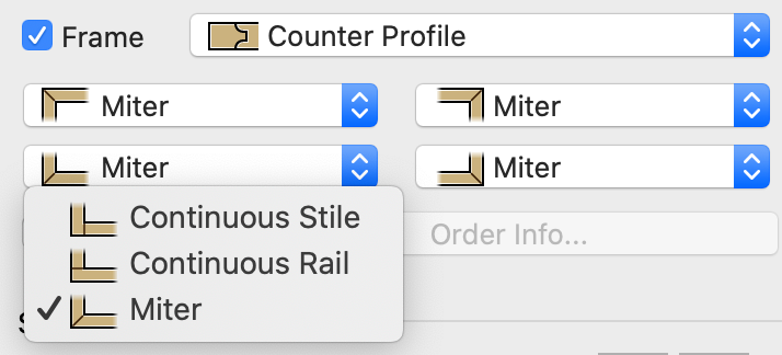
In "Set (Frame)" you first define the frame construction. Select whether the frame parts are to be connected by "Jack Miter" or "Counter Profile".
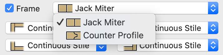
Note: Depending on the connection type "Jack Miter" or "Counter Profile", different construction options are created.
You can then specify for each of the four corner joints whether they should be connected "Continuous Stile", "Continuous Rail" or by "Miter".
Note: With the "Save" function (if available), you can save the settings as a preset.
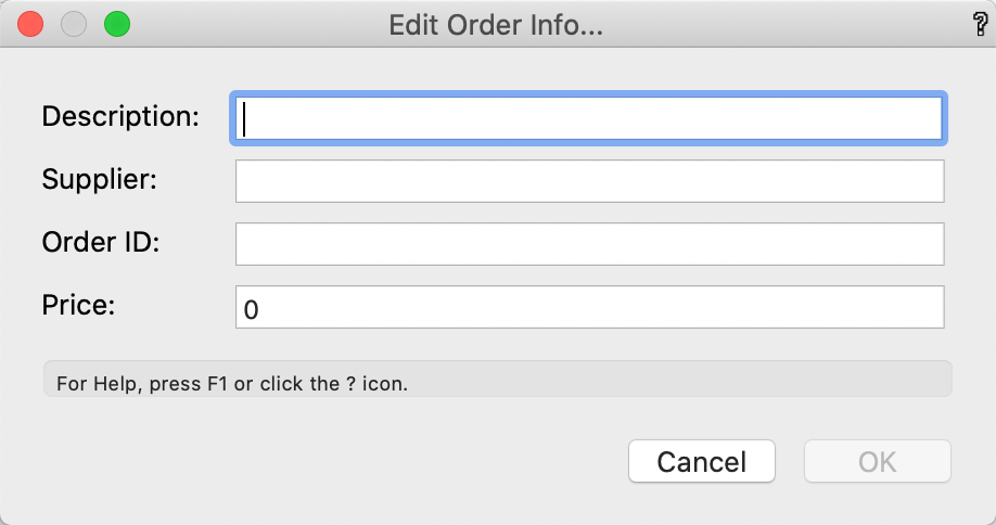
You can additionally declare a frame as a bought-in component and add corresponding order information. To do this, select the "Bought-In" checkbox.
Use the "Order Info" button to enter the "Description", "Supplier", "Order ID " and "Price" attributes.
In the "Set (part)", each of the four frame parts can now be configured in detail. To do this, click on the frame part to be configured in the "Preview" and make the desired adjustments in the "Set (Part)" block:
- Select whether the corresponding frame part should be executed as stiles/rails or not.
If you have added stiles/rails to a frame part, additional configuration options are available:
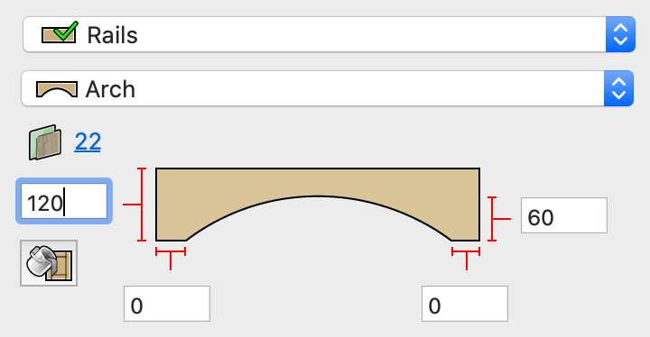
- Select the style of the corresponding stiles/rails from the "Plain", "Arch" and "Cathedral" options.
- Define the dimensions of the stiles in the input field. Depending on your selection, corresponding customization options are available.


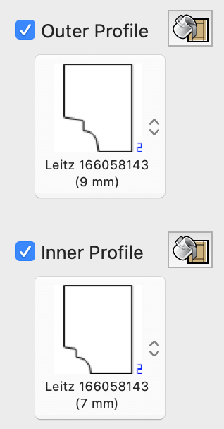
You can optionally assign a "Outer Profile/Inner Profile". Use the “apply for all” button on the right to define the selected profile directly for all frame parts.
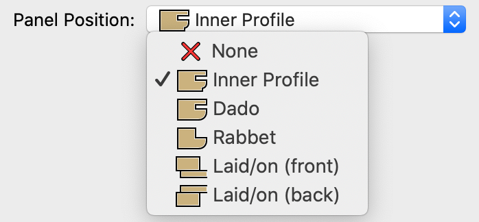
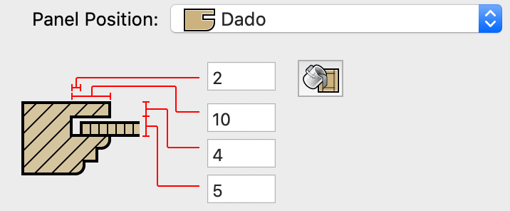
Panel Position
Choose how the frame panel should be attached to the frame stile or alternatively check the "None" option. If you have selected the "Jack Miter" frame design in the "Set (Frame)" the following options are available for the "Panel Position":
Depending on the option, parameters can then be individually adjusted in the input field.
You can divide the frame fronts with center stiles and different fillings as desired.
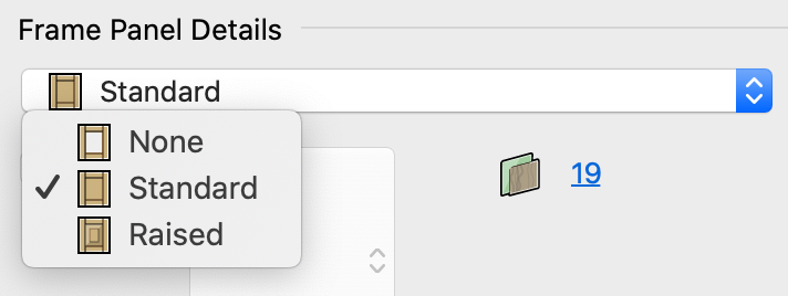
Set (Panel)
Click in the middle field of the preview, to adjust the Frame Panel Details.
Select an existing set or start configuring the frame panel type. The options "None" (filling), "Standard" or "Raised" are available. With the "Raised" option, a profile can be added by selecting the "Profile" checkbox.
Click on the material thickness button to change the material of the selected door. The individual assignment of materials is only necessary if you wish this particular part to be different from the material selected on the Construction tab. (Drawer details are configured separately, using the Drawer 3D tool.) You can fill in the Distance of inset front to shelf and the Distance of Front to carcass in the text fields in the graphics below the Front Details popup menus.
Note: Save settings as default value ![]()
If the „Save“ icon is available, you can save your set values as system-wide defaults (default value).
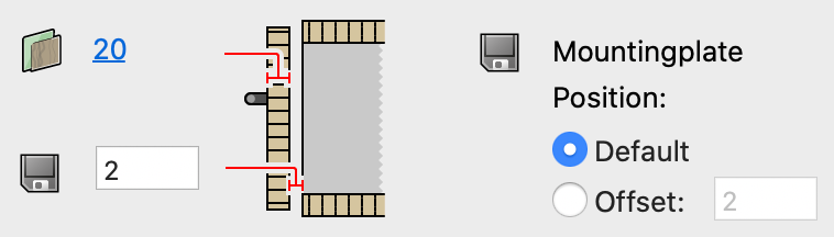
The mounting plate can be moved for doors and double doors. Positive values push the mountingplate towards the edge of the cabinet, negative values into the cabinet.
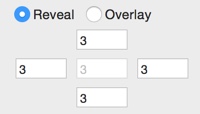
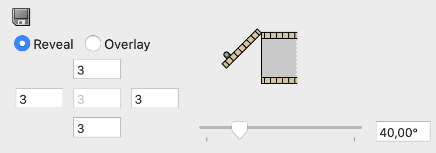
Reveal / Overlay
On this part of the dialog, you can adjust the reveal or the overlay dimensions for individual selected fronts. (Overlay = panel thickness + reveal). You can specify both for each shelf. The value in the center shows the reveal between double doors and this value is only active if a double door is selected).
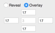
On the right side you can display your created fronts directly opened. Enter the desired opening angle in the input field or adjust the angle with the slider.
Adding profiles to plain fronts
If you have selected the "Plain" surface in "Front Details", individual profiles can be added to all sides of the front. To do this, check the box next to the "Profiles..." button. Now click in the white field below to assign a profile to all pages.
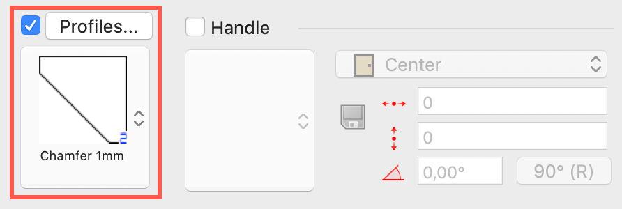
The selected profile is now assigned to all four sides of the front.
To customize the sides of the front (left, right, top and bottom), click the "Profiles..." button. You can now assign each page its own profile. The respective distances can be adjusted in the corresponding input field.
With this button, settings of a certain page of the front can be applied to all other pages.
When you have made all settings, exit the dialog with "OK".
Handles
With a door or drawer front selected, you can choose a handle symbols from the Handle popup menu. The popup contains handles from the «interiorcad/Cabinet Handles» symbol folder within the current document and from the documents in the «Libraries/Defaults/Cabinet/Handles/» folder. The handle position can be selected in the popup handle position to either the center of the door or at the upper or lower edge of the door. The handles are displayed in the preview. If a handle from a library document is selected, it will be imported to the «interiorcad/Handles» symbol folder within the current file. Imported handles are assigned to the class «XG-Cabinet-Handle».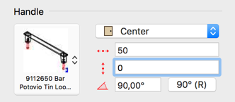
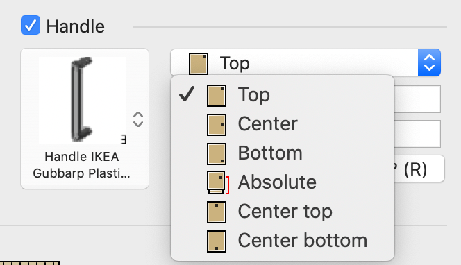
Select the handle position for your chosen front. Depending on the respective front, different handle positions are available. In the case of a door, for example, the handle can be arranged as follows: "Top", "Center", "Bottom", "Absolute", "Center top" and "Center bottom".
To set the position of the handle exactly, use the Handle's Vertical Offset and Handle's Horizontal Offset fields, to offset the handle relative to the value selected in the Handle Position popup menu. If you change the Horizontal offset, the value always moves the handle in the direction of the hinge. For the vertical inset, if the position is set to Top, the value moves to the bottom and vice versa. In the Centre position, a positive value moves the handle upward, while a negative value moves downward towards the bottom of the door or drawer front. An absolute value defines the handle position from the bottom of the cabinet.
Use the «Angle» field to rotate the handle. Handles are always rotated in a clockwise direction unless they are on a right hinged door. Handles on a right hinged door are rotated in a counter-clockwise direction. With the button right of the «Angle» field the handle is rotated 90 degrees clockwise automatically.
Type and depth of parts
If you select a part on the preview, the Part popup menu is displayed, and you can change the part type. Partitions can be constructed as stiles or can be hidden. Shelves can be fixed, movable or stretchers.
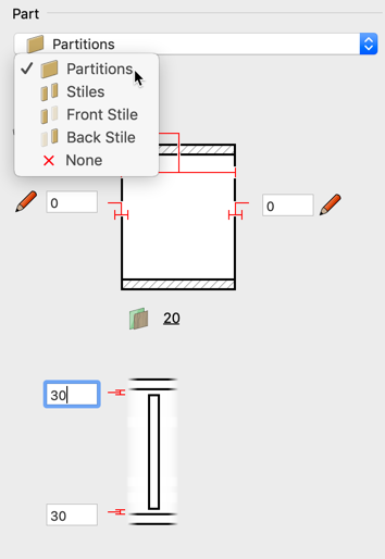
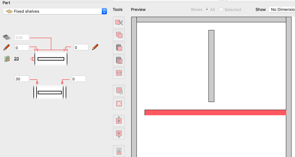
Top Figure
Use the upper text box to set the depth. The lower text boxes allow you to create an individual recess from the front or back. In case of top and bottom shelve, a small offset from below / above is also possible, so that the chipboard is not visible when rounded edges are used. Values with a calculator are calculated automatically. Clicking on one of the pens swaps this value to automatic calculation.
Bottom Figure
Here you can specify a top / bottom recess for partitions btw. a left /right recess for shelves.