Orientation of NC programs
VectorWOP 3D supports any object that is based on Custom Part 3D objects. The resulting NC programs are placed adjacent to the machine stops depending on the 2D paths that all Custom Parts 3D are based on. The lower x-edge of the path is put to the front machine stops (or back stops respectively) of the machine. The NC export places the part origin or the NC program to the lower left hand corner of a Custom Parts 3D‘s path.
The following graphics show the behaviour.
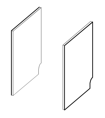
Consider two cabinet sides of a unit. To achieve cut outs, the cabinet was «ungrouped» and the «Clip Surface» command has been used to create the cut outs.
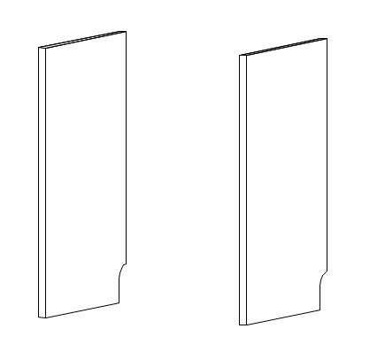
Double clicking each Custom Part 3D will show the following paths:


In woodWOP configured for a machine with the stops on the front, both parts will appear at the front left work bench as follows:


In Xilog configured for a machine with the stops at the back, both parts will appear at the back right work bench as follows:
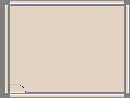

Simply explained, the path can be seen like it is placed on the outer sides of both Custom Parts, as well as Covering 2: