Editing Custom Parts
Editing Custom Parts in the Object Info Palette
Rotation
By entering a rotation angle in the Object Info Palette, a Custom Part can be rotated around its center point. Positive values rotate counterclockwise, negative values rotate clockwise.
Rotate X, Y, Z buttons
With the "Rotation" functions the Custom Part can be rotated 90° around its X, Y or Z axis. This allows you to start with a Custom Part drawn on the ground plane and rotate it to a different orientation with just one click. You can also find this as a command in the menu «interiorcad > Custom Parts».
Swap Machining Sides
Changes the machining sides on CNC
Swap Dimensions
When the Custom part is created, Length, Width and Thickness are detected automatically. Note:- The default Thickness is always the smallest value. Here appropriate mapping can be selected from the menus.
Change of dimensions in the Object Info palette
If a Custom Part is rectangular a length and a width field are shown in Object Info Palette. If a Custom Part is not rectangular, you can double click the Custom Part to edit its path or use the Reshape Tool directly with the custom part. You can also draw 2D objects directly on top of a custom part and use "Clip Surface" and "Add Surface".
With solid wood, the thickness can also be changed; for other materials, this is only possible with the Dialog version. (Thickness = Thickness, Execution = Construction)
Construction Area
Enter a name for the bill of material(=Cutting List)and directly select a material specification and the carrier material (= Board).
All other material settings are displayed in a notification area below and adjusted in the dialog Construction .
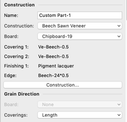
The grain direction for the board and the coverings can also be changed in the Object Info palette. If no coverings are selected, only the board can be adjusted. The "None" option means that the direction is chosen automatically. The "Length" and "Cross" selections are in relation to the longest side of the part. If the component is changed, the grain is recalculated and, if necessary, rotated. The grain direction not only has an optical effect, but also changes NC Export and cutting list. For example, it is possible to run the grain of the board and coverings opposite to increase stability.
Construction
The Object Info palette provides a button with which to edit the construction of Custom Parts. This enables you to set and edit information such as the board‘s material, the coverings, edge bandings, and finishings. For solid wood, it is also possible to specify the thickness. The assigned materials will automatically set textures for rendering and appear in the various lists, such as cutting lists, board lists, or costings:
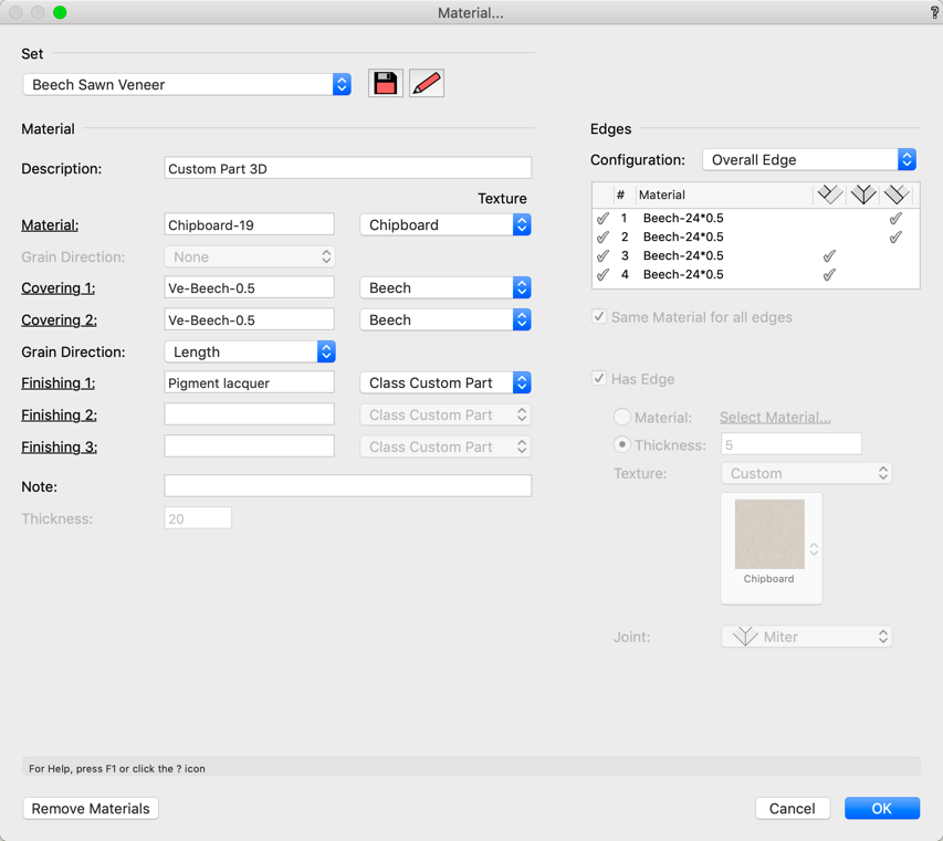
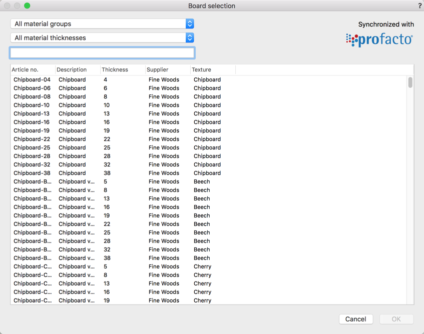
To change the material you can either enter the material abbreviation in the text entry field or click on the link to choose from all materials of this type. All selection dialogs can be filtered at the top via the drop-down menus:
The dialog supports multiple objects being selected. A dash indicates that different materials are used by the selected objects. Replacing the dash with another material will apply this information to all objects selected. The applied information is also displayed on the Object Info palette. If any fields are left blank, they are not displayed on the Object Info palette, so that they don't use valuable space.
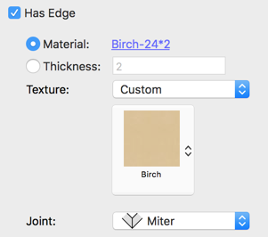
The Custom Part can have an edge all around or in parts. The configuration menu allows you to select frequently needed settings directly.

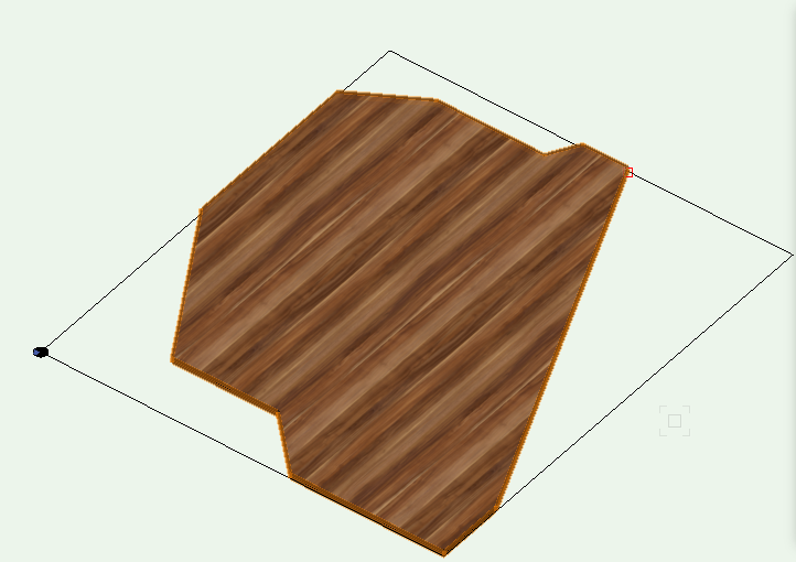
As shown below, you can also configure each edge individually. If an edge is selected, it is highlighted in red in the drawing area.
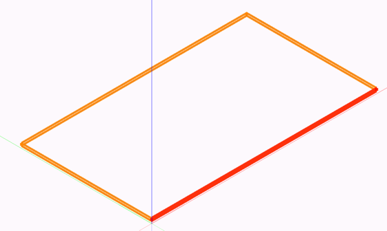
Clicking in the first column disables the selected edge. You can define the joint in the three columns behind the material name. You also have the same setting options below.
Textures
interiorcad tries to apply textures automatically, while allowing the user to override the automatically chosen values. The mechanisms used read as follows:
- No texture
It is possible to tell a component not to use any texture at all. - Class Texture
The components of the Custom Part will use the texture of the classes they belong to. - Dedicated Texture
The user can assign a texture of the current document to the component. Textures can be imported directly from the library for the user‘s convenience. Selecting a material using the loupe button will automatically import the texture from the library when necessary and assign it. If possible, selecting a material will cause interiorcad to use the class texture.
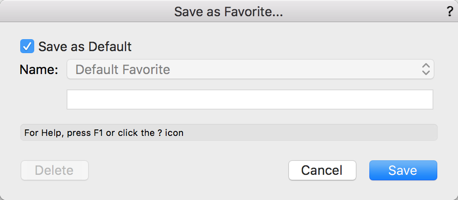
Save Construction als Favorite
Use the Save button to save favourite lists of frequently used material combinations.

If you choose the Default Favorite instead of your own preset name, your construction settings will be used automatically for all new Custom Parts.
Checkbox »3D Details«
The «Object Info» palette of the Custom Part contains a «3D Details» checkbox. When checked, the Custom Part is modelled with its edges, coverings and board in 3D. Also the drillings, which are connected with the Custom Part, are shown in 3D. If the checkbox is turned off, there is only one texture for edges, coverings and board material shown, veneer and drillings are no longer shown. This checkbox should only be activated if necessary, as the level of detail could adversely affect the performance of the software.

Checkbox »NC Details«
If this option is turned on, you can see how a polygonal custom part is placed on the CNC and which is the main and which is the secondary processing side.
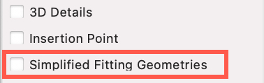
Simplified Fitting Geometries
You can switch between detailed or simplified hardware geometries using the "Simplified fitting geometries" checkbox. This option displays less detailed geometries, allowing for consistently smooth performance on large projects. It can be configured individually per component, carcase furniture or drawer.
Parameter »Orient along longest edge«
When this setting is enabled the path of the Custom Part will always be oriented along its longest edge: The Custom Part's longest edge is at the stop of the CNC machine.
This avoids large waste during formatting of the part on the CNC machine especially for polygonal parts.

Parameter »Insertion Point«: Visualise the position of the component.
By fading in the "origin" is when changing the properties Length/Width/Thickness respectively Width/Height/Depth. The info palette shows in which "direction" the
adjustment of the dimensions has an effect. (Origin = Insertion Point, Infopalette = Object Info palette)
Cutting lists and NC export
By clicking on the Cutting List and NC Export buttons, you can export the selected Custom Parts.
Creating Section Viewport Preferences for Cabinets: Assigning hatches to Custom Part 3D classes
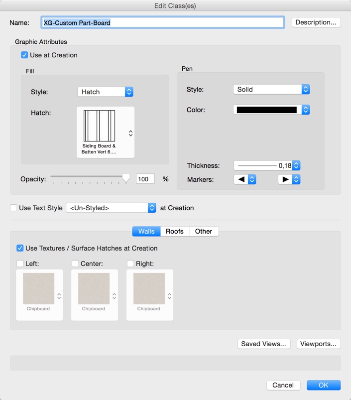
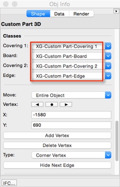
All Custom Parts - also the ones in cabinets - use common classes for boards, coverings and edges. On the Navigation palette, right-click on the class and choose Edit to assign hatches.

These hatches will be displayed when the part is sectioned in Section Viewports.
Before you create a section viewport as used in Vectorworks, you will need to activate the 3D Details checkbox for all Custom Parts. If some Custom Parts need to be displayed with other hatches, assign these objects to different classes in Object Info palette. Ungrouping a cabinet makes its Custom Parts editable. So it is also possible to change the class of a single Custom Part 3D within a cabinet.
Additional Custom Part functions
Mirror components
You can use the "mirror" tool for Custom Parts. The NC output will also produce a mirrored workpiece, but the internal path of the Custom Part is not mirrored.
To change this, use the Clipboard to copy the path from the original object. Place the path in the drawing area. Mirror the path and create a new Custom Part from it.
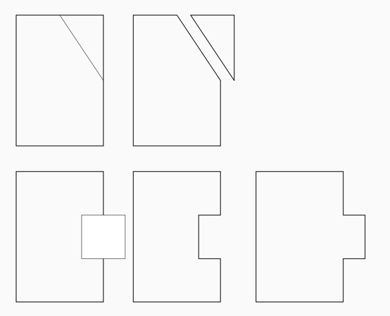
Changing the shape by editing the path
To edit the part's path, double-click the edge of the Custom Part. The path opens automatically for editing.
Change the shape by surface operations
You can change the formatting (outer contour) of a part quickly and selectively by using the Modify > Clip or Add Surface commands. To do this, place rectangles, circles, ovals, polygons, polylines, lines, or parts on a part and run the command. The contour will be adjusted. Lines will split the part.