Creating custom libraries
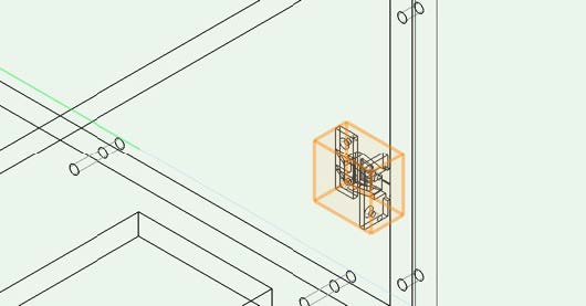
Manual placement of fittings
In case you need fittings that don't come with interiorcad's built-in library, it's easy to add those to your own library. An easy way to do this, is to first import the 3D geometry of a fitting. Then, create a symbol for placement in your document. You can find an example of how to do this in the introductory tutorial 'Production Realism'. This procedure will work for all fittings and is easy to achieve. As opposed to placement via an interiorcad tool, the insertion of custom fittings is done using the standard Vectorworks Symbol Insertion Tool.
Placement with interiorcad fitting tools
To create or change fittings, choose interiorcad > Fittings > Edit Fitting Libraries.
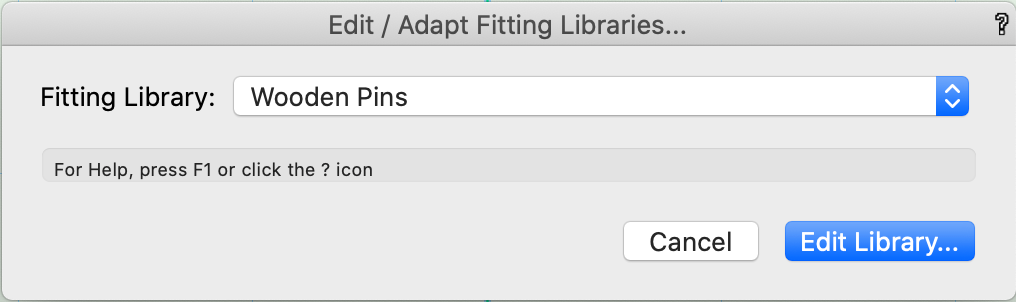
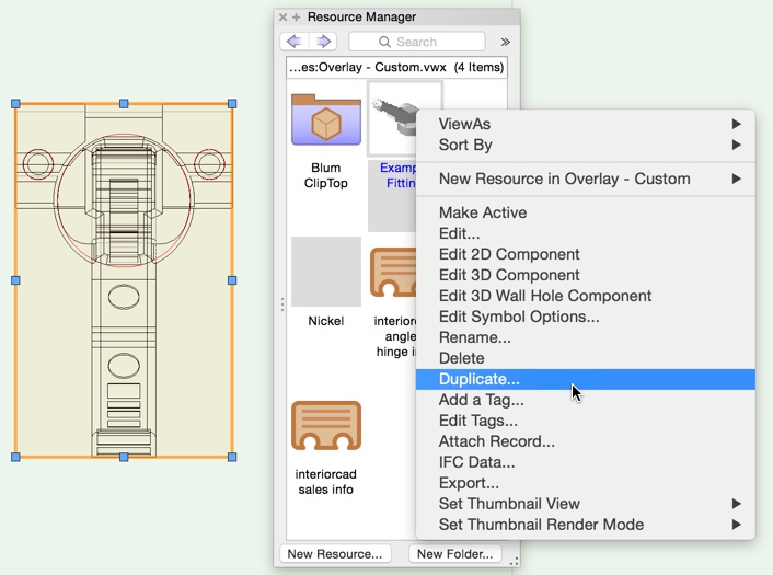
This command opens a library file for the selected type of fitting from within the user folder. New files contain one example symbol for the fitting type, which can be duplicated and adjusted easily.
Note: The files in the user folder should contain only your changes. Don‘t copy all fittings there. Otherwise, you won't automatically get updates for the libraries delivered by extragroup.
The duplicated symbols may be named as you wish. If several fittings (e.g. hinges and mounting plates) belong together, they must be assigned to each other using the library folder. This means both parts must be located in an identically named folder.

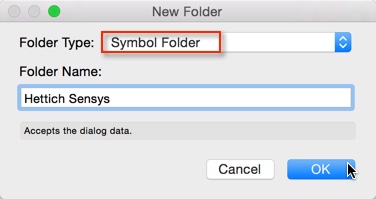
To create a library folder, in the Resource Manager choose <<New Folder>> and select the Folder Type <<Symbol Folder>>.

Always edit the «3D Component» of the interiorcad library symbols.

The library symbols consists of:
Custom Vectorworks constructions, which are the base for the realistic representation of parts
Machining (e.g. drillings, center punches, etc.)
Possible behavior control for tools (e.g. grid)
Sales Data for part lists and calculations
You don’t have to create the custom Vectorworks construction yourself. Almost all of the larger fitting suppliers offer 3D geometry to download. The best format, if available, is the Parasolid format (*.x_t). Otherwise you can import DXF/DWG or STEP files in their latest release. You only have to drag the files into Vectorworks and accept the import dialog using the standard settings. Note: Box Objects will be moved to their own resource folder in the current document.
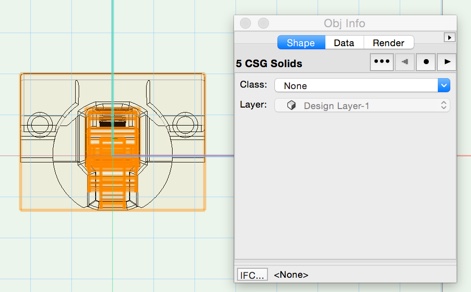
Depending on the geometry supplier you are advised to try different file formats. To obtain the best performance from interiorcad, it is best to use solid geometry when creating fittings. For this reason it is recommended that after you import the geometry, select it and look at the Object Info Palette and note the type and number of objects. Press «Ctrl+U» (repeatedly if necessary), to ungroup the geometry until the selected objects consist only of solids. You should then group the remaining parts again using «Ctrl+G», to create a single selectable object.
Some imports will result in a large number of objects after ungrouping.
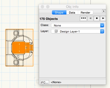
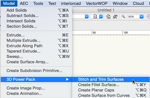
It's necessary to reduce the number of objects as much as possible. Often, Vectorworks will be able to convert these objects into solid geometry, using the option «Model > 3D Power Pack > Stitch and Trim Surfaces».
Check the geometry after using this option. Sometimes the geometry will be changed a lot or it might not be possible at all to convert the object into a solid. In this case try the option «Modify > Convert > Convert to Mesh». The resulting geometry will not be as beautiful, but you will be able to use it to create parts for interiorcad.

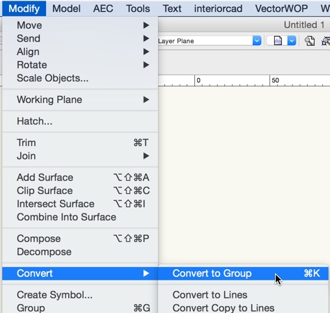
In some cases, the imported geometry will be grouped together as a symbol, and may also contain nested symbols. Symbols must also be ungrouped so that interiorcad doesn’t treat them as an individual part of the library. Select the imported geometry and run the command «Modify > Convert > Convert to Group» («Ctrl+K»).
Once the geometry has been prepared using the above methods, the resulting group can be copied easily into the 3D element of the duplicated symbols in the interiorcad library document. The next step is to position and rotate them correctly.
To rotate the objects you can use the shortcuts:
Ctrl+L for a 90-degree left rotation
Ctrl+Shift+R for a 90-degree right rotation
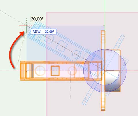
Use the «Top» and «Left» standard views to view the geometry in detail and use the shortcuts to bring the object into the same rotation as the example. Use the Rotate tool on the Basic palette to rotate the geometry to its appropriate rotation—for example, you may need to do this to represent angled hinges accurately.
Click once to select the point, around that you want to rotate around, then use a second click to select the start point of the rotation. Now you can rotate the object using the mouse or using «Tab» to enter a rotation angle. Click to complete the rotation.
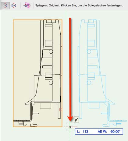
Some accessory parts are available mirrored: In interiorcad. For example, drawers will always be created as the left accessory parts (the left drawer profile, the left runner). Sometimes only the geometries for the right accessory parts will be available. The graphic shows how to adjust a drawer profile using the tools «Mirror» and «Duplicate».
Next, move the fitting into the appropriate position. There are few basic rules:
An axis (usually the x-axis, but for drawers the z-axis) is the surface of the panel or the connection area between two components. The part of the fitting, which will go into the panel, lies under or left of this axis.
All CNC machining, like drillings, center punches, etc., must vanish completely in the panel and therefore be placed under or left of this axis.
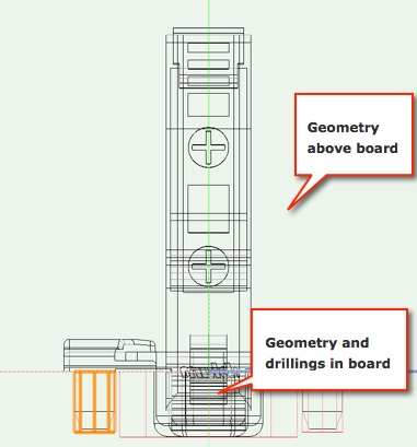
All CNC machining must be inserted in the panel. The CNC drills into the panel and not out of it. You can check the direction by adjusting the depth in the Object Info palette. If for example a drilling increases underneath/left of the axis then the drilling direction is correct. If the drilling goes into the fitting you have to mirror the drilling.
The CNC machining is most important element for accurate production. The geometry is used for graphic presentation. You should always create the correct drilling pattern first.
Note that, unless otherwise stated by the supplier, all delivered fittings with drillings, which you use to screw something in, come with a little smaller laid out diameters and are a little longer then necessary for the screw. If the drilling is used to push something in, the diameter is laid out a little bigger (unless otherwise stated). You can adjust here as necessary.
You can duplicate and adjust the example symbol or, especially if you want to create several fittings, use a symbol, which already has the correct drilling pattern.
Duplicate the appropriate symbol, adjust the drilling pattern if necessary, put the imported geometry next to it and adjust using rotations and mirroring. Afterwards delete the old geometry.

Afterwards you can move the geometry onto the drilling pattern. For this you need to work in 2D mode. Therefore first move using the «Top» view and then the «Left» view.
In the view «Screen Aligned» the mouse connects to a 3D point and moves the selection not only in 2D, but also all other invisible dimensions. Change to «Screen Plane» in the View bar:

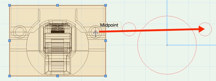
The easiest way to position a fitting is to move the drilling center of geometry onto the appropriate drilling center of the drilling pattern. The mouse connects better in simple structures than in more complex ones. For example you should move a hinge using the simple drilling hole and not the cup hole.
Sometimes geometry delivered by the supplier is inaccurate. You have to accept that the geometry doesn’t fit 100% to the drilling pattern rather than to move them.
If it is difficult to grab the geometry, you can use the «Move by points» tool. - for example to move along the z-axis.
For all fittings you can find database entries for the part lists (sales data). For many fittings it is also necessary to specify further technical data for the correct positioning. This information will be assigned to the geometry using the Data Tab in the Object Info palette. If the geometry consists of several bodies, you should group them using «Ctrl+G». Select the geometry, activate both Record Formats and select the Field and change its content using «Record Info».

Sales data is the same structure for each type of fitting:
Description shown in the cutting list
Supplier shown in the cutting list
Order-Number
Price
Why reinvent the wheel? Use already existing fittings!
Before you create new fittings it makes sense to explain a few connections between the fittings. This will simplify this task:
Many fittings are offered in variations, which only differ in their sales data and maybe in the rendering structure. For example connectors are often offered as plastic version, or hinges are offered with different functionalities or different ways to mount them. But the geometry and drilling patterns remain the same.
For many fittings there are only a few different drilling patterns, which are repeatedly used (e.g. hinges, handles).
In these cases it makes sense not to adjust the example symbol over and over again. Instead you should duplicate a similar object. You can find the supplied symbols in Vectorworks at «Libraries/Defaults/Custom Part» or at «Libraries/Defaults/Cabinet». If you open such a library document simultaneously to your own library document, you will be able to export the appropriate symbol into your own library document using a right click. Then you will be able to adjust it. Please make sure you always create duplicates and do not adjust any of the supplied data. This avoids your customizations being overwritten when updating your software.

Filter fittings and materials
Whilst creating custom fittings or materials, there is the option to minimize the view as follows:-

Create a new connector in your library (for example dowels)
Please read the introduction to how to create new fittings first.
Create, as described above, a copy of the example symbol in your dowel library document. The origin of the symbol will determine the insertion point of the dowel. The drillings must be inserted in both directions of the insertion point so that they connect correctly with the components. The graphic shows the components of each individual dowel.

Editing Existing Invis / Create New Invis
Please see below how to detail fasteners:-
With Invis connectors it must be noted that currently, Connector Sets are supported (Stud and Element). Other Stud / Element combinations are not possible. The Element must lie above the X-Axis and the stud must lie below the X-Axis. As a result, the drillings for the Element are shown upwards from the X-Axis and the drillings for the Stud are shown downwards from the X-Axis.

Editing Existing Screw / Create New Screw
Please read the introduction to how to create new fittings first.
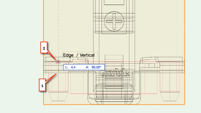
Make sure the connector has a drilling for each Custom Part that will be connected with the connector if it is necessary. Sometimes the drilling for the face side Custom Part is not needed. In this case only the drilling for the plain side is needed. The drilling for the plain side Custom Part has to be set the option »Drill Through« and the drilling for the face side Custom Part has to be the length with an desired addition of the desired connector.Geometry and drillings has to be drawed in negative Z-axis direction. If you want to create a screw with a head (see below picture 1) you should move only the geometry in positive Z-axis direction. The screws can be found in the document «Screw.vwx» which is located in the folder «Screws».


Creating Connectors in Library
Please read the introduction to how to create new fittings first.
A connector exists of a connector bolt and a connector housing. The allocation of a series will be established using the library folder.
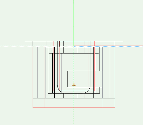
In general you need 2 drillings for a bolt symbol, which lie at the origin point as shown in plain view. Using front view one drilling points down from the horizontal axis into the side panel, the other up into the front panel of the other component. For very short bolts you can leave out the front panel drilling, if it is completely within the connector housing. For endbolts you must mark the side panel drilling as clearance hole.
The connector distance will be defined on the z-axis using a »3D-Locus«. You may only place one auxiliary point, which can, depending on the bolt, also lie over the geometry. The auxiliary point is the distance to the midpoint of the connector housing. The z-value of the »3D-Locus« will often be named drilling dimension.

Connector Housings
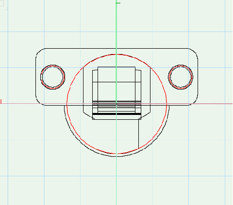
In «Top» view
The housing has to be positioned so that the center of the drilling is on 0.
The aperture for the Bolt has to be at the bottom. This aperture is marked with an arrow and the arrow has to point down.
Other drillings has to be positioned relative to the housing drilling.

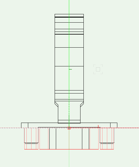
In «Front» / «Left» view
The part of the bolt, that is situated outside the Custom Part has to start from 0 and drawn above 0, the other part has to be drawn below 0.
All drilling for the connector has to start from 0 and the direction has to be from top to bottom. If needed the drilling could have set the option «Drill Through». Check drilling diameter and depth here also.
For bolt positioning an auxiliary point (3D-Locus) is used here. This point is located on the Y-axis inside the housing (X and Y values are 0). The (negative) Z values defines the distance of the bolt. (No other 3D locus has to be placed in the symbol.).

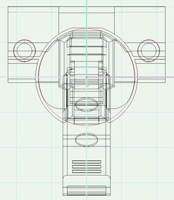
To position the bolt correctly, use a »3D-locus« on the z-axis. The distance to the horizontal axis is negative and indicates the distance to the bolt.
In the »Left« view you can check all drilling positions.
Creating hinges and mounting plates
Please read the introduction to how to create new fittings first.
A hinge exists of a cup with hinge arm and a mounting plate. For every supplied type of accessory there is an individual library file sorted by the type of mounting. In each you will find the symbols sorted by series in the library folder. For a correct assignment the hinge and the mounting plate must be located in the same library folder.
Create the geometry and machinings for Hinges
In «Top» view
The hinge has to be positioned so that the center of the drilling for the hinge cup is on 0.
The door hinge has to be at the bottom..
In «Front» view
the part of the hinge, that is situated outside the Custom Part has to be drawn above 0.
The part inside the Custom Part (including the drilling) has to start from 0 and drawn below 0
Other drillings have to be positioned relative to the hinge cup drilling.
First create the drilling pattern as shown in the supplier manual and then move the geometry at the appropriate place.
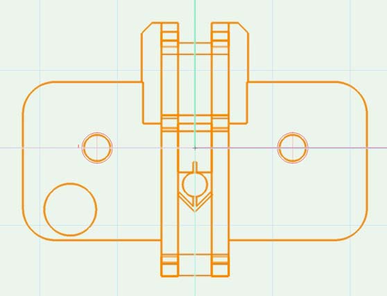
Create the geometry and the machinings for Mounting Plates
In »Top« view, the mounting plate lies centered on the y-axis at a height, that the drilling is the normed 37mm away from the horizontal axis. Usually you only have to move the geometry into the correct position. The drillings remain unchanged. Here again the door overlay is at the bottom.
In «Front» view the part of the mounting plate, that is situated outside the Custom Part has to be drawn above 0, wheras the part of the mounting plate inside the Custom Part (including the drilling) has to start from 0 and drawn below 0.


Technical data for cup hinges and mounting plates
To place hinges and mounting plates correctly to the mounting situation you will need few technical data first. These can be found in the Data Tab.
For a cup hinge you need several information of the supplier catalog:
Door overlay
Cup distance
Mounting plate distance
Min. and max. cup distance
You need only one connection between door overlay, cup distance and mounting plate distance of the technical data from the supplier as well as the min. and max cup distance. All other values of the cup distance table will be calculated by interiorcad. Here an example using the Blum catalog:

For mounting plates only the mounting plate distance is necessary. Just enter the mounting plates you want to use later. interiorcad will deliver the relevant cup distance and mounting plate distance for the selected overlay using the tool «Hinge». The table will look different for the company Hettich but the relevant data can still be extracted without problems. Here again, you only need one connection from the table and the min. and max. cup distance of the hinge. For the hinge ratio input it is irrelevant whether a mounting plate with the inserted distance exists and whether you want to use it. The values will be automatically calculated for your mounting plate.

Create new angled hinges
Please read the introduction to how to create new fittings first.
For angled hinges the opening direction is important. Library files for hinges, mounting plates and spacers are seperated after opening direction. With positive spacers you can increase the angle by 5 degrees, with negative spacers you decrease the angle by 5 degrees.
Exactly as for standard hinges you create the ratio between hinge and mounting plate using the library folder. For a better overview you can create sub folders for the angles. The appropriate positive and negative spacers are stored in the hinge using the article ID.
Adjust the library documents suitable to the opening direction. Best you duplicate the example symbol. You can extract the position there.
Example: opening hinge
In «Top» view 0/0 is in the center oft he cup hole.
In «left» view the cup hole is centered and underneath of 0. A hinge with positive angle points right, a hinge with negative angle left.

In «Front» view you can see the centered position of the drilling underneath 0.

Example «Opening Mounting Plate»
In «Top» view the mounting plate is placed in a way that the y-axis runs centered between the drillings and the x-axis runs centered through the drilling.
In «Front» view the mounting plate is placed on 0/0. The center punch lies completely under 0/0.

Example «Opening Spacer»
The placement of the spacers is identical to the mounting plate. You have to assign the appropriate article ID as name to the spacer symbol, as it will refer to the hinge later.
![]()
![]()
For the appropriate placement using the fitting tools you need to collect the following technical data:
For spacers, the angle
![]()
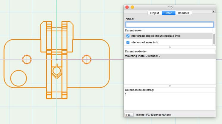
For mounting plates, the mounting plate distance.
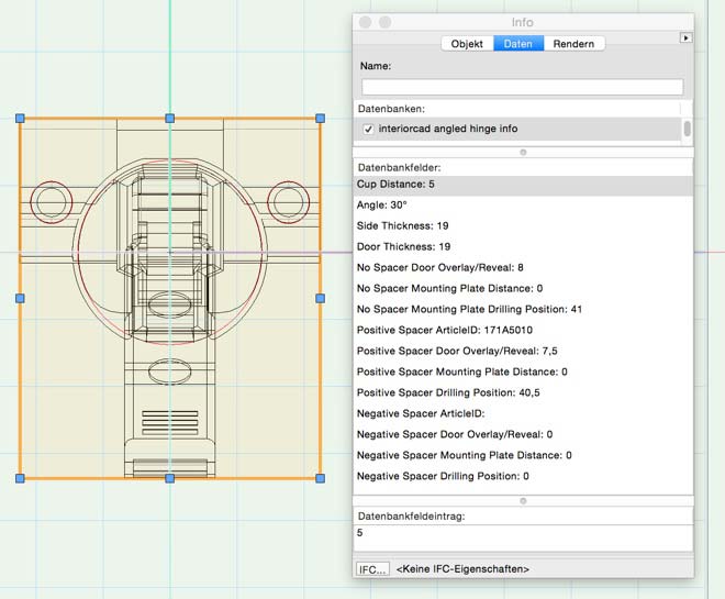
The most data will be collected about the hinge. These data are described as follows:
«Angle» - The angle the hinge is made for.
«Side Thickness» and «Door Thickness» - the thickness of the side panel and the door. For angled hinges the material thickness, the hinge is made for, differs. Try 19 if the suppliers don’t give any other information.
Adjust positive spacer under «Positive Spacer» and negative spacers under «Negative Spacer». «Article ID» is the relevant article number. Are there no positive/negative spacer the respective entries stay empty. Angled hinges support in each situation with/without spacer exactly one combination of «Door Overlays», «Mounting Plate Distance» and «Mounting Plate Drilling Position»
You have to take the values of the supplied technical data of the suppliers, for example for Blum. In this example only the overlay changes for the use of a +5 degrees spacer. Depending on the hinge the mounting plate drilling position, the cup distance, the mounting plate distance or the thickness of the side panel or door can change. Therefore you have to control al values.
With Hettich, you can measure the data from the printout / catalog (Caution, when printing from the on-line catalog: Many printers adjust the page to the printable range.The values read then, are no longer correct). Unlike standard ribbons, the angle band can only be used with a specific mounting plate and a certain impact. In this example, you need to take a mounting plate with a thickness of 0 and set an overlay of 9. The article number can then be taken from the selected mounting plate.

The interiorcad drawer system.
General tips how to create fittings you can find at the section «Creating new accessory parts in Vectorworks interiorcad».
The interiorcad drawer system consists of:
drawer profile
back fixings
Front panel
slider
longside rail
For each accessory part there is a library document. The connection to a model or series is created through folder. To use a drawer, it needs to be configured in the library folder Drawer. The more general the folder is the more general the slider will be used. This means if there is a slider in the folder Tandembox then it will be also used for the groove, which is located in the subfolder Tandembox-invito. Otherwise a slider located in Tandembox-antaro would not be used.
Create Drawer Profiles
The 0/0 point of the drawer profile symbol is the front bottom left point of the drawer opening. The drawer profile needs to be located in the top/right quadrant. The groove position results of the supplier data. Here for example Blum:
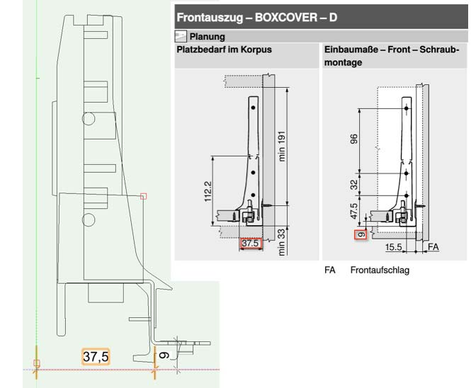
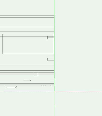
In «front» view the front bottom left corner of the drawer bottom will be moved to the coordinates X=37.5 and Z=9. The y-value is 0 as shown in the «left» view:
That grooves can be assigned correctly they must be organized in the correct library folder. The folder structure, which is used by interiorcad, is as follows: type of slider (Tandembox, Metabox), letter of model series, model ID.
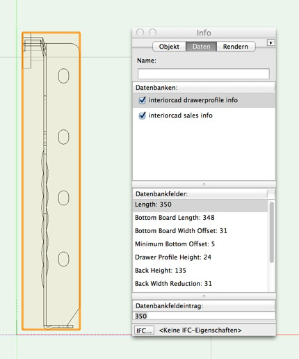
These Technical Information can be changed on the Data Tab of the Object Info palette:
Length of drawer profile
Length of drawer bottom board
Drawer bottom board width offset
Minimum drawer bottom board z offset
Drawer profile height
Drawer back height
Drawer back board width offset
Supplier-ID for back corner clip
Continuous drawer base
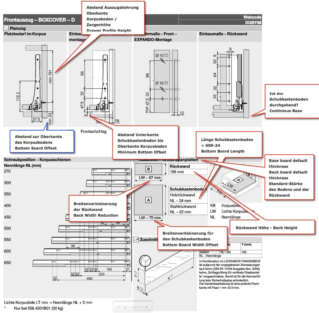
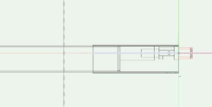
In following graphics you find examples of Blum. The red marked values are tech data for the groove. The blue marked values are tech data for the slider.

Sliders Library
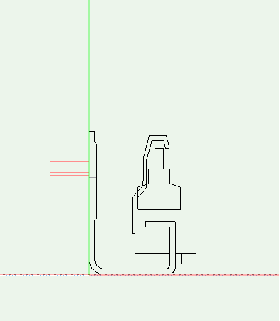
In «Front» view the origin is the front bottom left corner of the drawer. The mounting of the slider is therefore left of the vertical line. The slider will be moved by the supplier indicated value in y- and z- direction. You will find the drilling position in the supplier catalog. For example Blum indicates the third drilling.

In your duplicated document, delete all drillings except one. Select the last drilling and insert the in the catalog given values in the «Object Info» palette.

Then, using «left» and «front» view, you can move the slider that the drilling is placed as appropriate.

Is the drilling pattern given, as shown in the graphic, you can create congruent copies of the drillings using the «left» view and pressing «Ctrl+Alt+V» and «Ctrl+C». Also, you can insert the distance to the first drilling as calculation into the «Object Info» pallet.

So that you can assign the slider correctly you have to place their slider type (Tandembox, Metabox), their series and their length into the library folder.

Create Underfloor Sliders for Wooden Drawers
Underflloor sliders for wooden drawers are made in the same way: As the wooden drawer requires no additional accessories, here some additional technical information should be recorded. In addition, drillings and contours for the front and back are included in the drawer symbol.

This technical information needs to be recorded:
Slider Length
Slider Length Addition: The sum of nominal length and the addition make the space requirement of the drawer of the compartment (= min. Internal cabinet depth)
Bottom Board Offset is the distance between the bottom of the compartment to the center of the drilling.
Drawer Base Offset is the distance betewen the bottom of the comartment and he drawer's bottom panel.
Dado Distance From Bottom Min - Maxis the minimum / maximum distance of the drawer bottom dado to the lower edge of the drawer side. If only one value is given, this is taken as the minimum and maximum distance.
Minimum Top Offset is the minimum top offset of the drawer from the top of the compartment. Unless the manufacturers make no explicit indication here, we expect 5mm.
Drawer Length Reduction is only necessary if the length of the drawer side is smaller than the slider length. E.G. the length of Grass drawer is 10mm smaller than the sliders. Normally there is no difference - Then the value is 0.
Drawer Inner Width Reduction indicates by how much the internal width of the drawer is smaller than the inside cabinet width.
The following figures show how these information are taken from the Hettich catalog.


Creation of front fixings
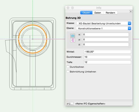
The position of front fixings in «front» view depends of the position of the center punch. In this example you can read out the position of the center punch directly. Inset the center punch at this position and then move the front fixing to the appropriate position using the «front» view.

In this position, using «left» view, you can see that the y-value equals «0». The center punches must be set to «-180 degree» that they show in the correct direction.

The other center punches can be created using the «left» view by pressing «Ctrl+C» and «Ctrl+Alt+V» to create congruent copies and by moving these to the correct position in the Object Info palette. To complete the steps you only have to add the «Sales Data» in the Tab «Data» and move the symbol into the correct folder. The gathering of further technical information is not necessary.
Creating new back fixings
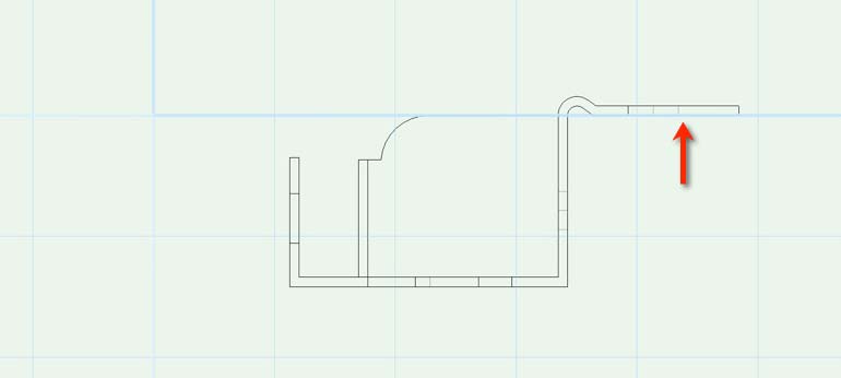
You can calculate the distance of the back fixing to the «front»: If the supplier data indicates the height of the back panel and the distance of the top drilling to the left top corner of the back panel you can calculate as following:
z-coordinate (height):
Distance base – Drawer: 9
+ Possible base of the drawer: 0, as not continuous
+ Height of back panel: 199
- Distance top edge: 8
= 200
x-coordinate
Distance back panel to the drawer side: 87/2 = 43.5
Distance to the side of back panel = 9
= 52.5

In «top» view you need to move the back fixing as appropriate so the back panel is directly on the x-axis. If you place center punches or drillings they have to go from top to bottom.
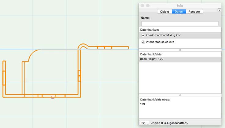
As tech info you have to record the back panel height:
Capture longside rails
The position of the longside rails are assigned in the back fixing library folder using «3D-Locus». The x- and z- coordinate have to be read off in the catalog. Y is set to 0. For each longside rail an 3D-locus is created. In your own library document the longside rail is now placed with the drilling insertion point onto the origin. Using the «front» view it looks as follows:
And like that using the «left» view:
As usual you have to record the Sales Date for the longside rail.
Drawer 3D Tool
With the Drawer Creator 3D 
If you double click the Drawer 3D Tool for the settings it will placed correct automatically.
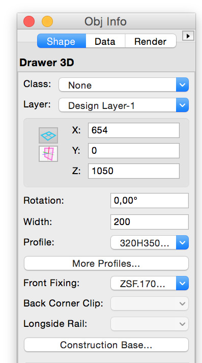
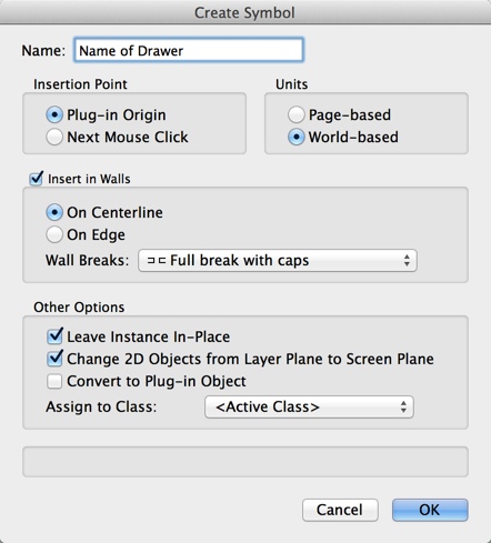
In the settings you can choose a Drawer Profile, the Front Profile and Inset and materials for the bottom and the back. After clicking ok, choose Modify - Create Symbol and fill in the name of the drawer.
Build your own handles
The handle library in interiorcad can be expanded any time. A complete handle symbol contains the 3D-geometry of the handle, drillings necessary for mounting the handle and some commercial data. You can also duplicate existing handle in the library document and adapt with your needed modifications.
Here is an example that shows how to create a fully working handle for interiorcad:
Create handle geometry
The geometry must satisfy some conditions, so the handle and its drillings can be placed in the right place when creating a cabinet.
The handle needs to «stand» with its drillings on the X/Y layer, so in front view the handle shows up and the drillings down..
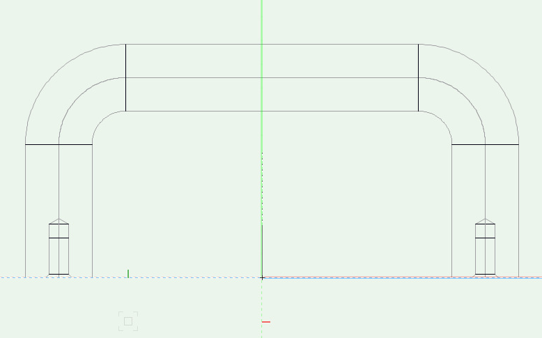
The handle needs to be centered to the origin, so in top view the origin is visible at the middle of the handle.

The positioning of the handle on the cabinet depends on a rectangle through the middle of all outside drillings. So make sure to consider this at asymmetric handles.
Drillings on handles
To create appropriate drillings in the workpiece for the handles in NC export, drillings have to be assigned to the handle. For the positioning of the handle the position of all drillings is important.
Place in «top»view a drilling in the document.

Move the drilling (still top view) to the wanted position at the handle.
Check the position of the drilling in front view and «right» view.


Enter the drilling diameter and set the check box «Drill Through».
Drillings will start from inner side of doors or drawer fronts if you set the check box «Invert Drill Direction».
If the handle needs multiple drillings, change to front view and duplicate the first drilling to the other positions.
Check the position of the drillings again in »front« view and »right« view.
Commercial Data for Handles
Commercial data is stored in a database, accessible through the «Data» Tab of the «Object Info» palette of the object. The database layout will be copied to your document as soon as you use a handle in a cabinet..


Select the handle geometry set the check box at «interiorcad sales info» in the «Data« tab. Enter the data into the four database Record Fields.
Using own build handles from library
To use the created handle in the Cabinet PIO create a symbol from the complete geometry, handle and drillings. At symbol creation please use the following settings.
Check and correct the geometry and insertion point of the newly created symbol.
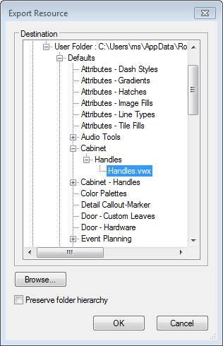
If your user library folder does not contain the «Handles.vwx» in a path as shown below, please choose interiorcad > Fittings > Edit Fitting Libraries and choose the handles to create a new library document in your user folder. Then right click on the newly created symbol and «Export...» to the following location:

Create legs
Legs consists of
- The foot itself,
- mounting plates,
- glides
- accessories
Feet
Feet are placed based on the geometry. The geometry must be created centered at zero level (z=0). If there are no mounting plates, the CNC edits are directly included in the feet file.
Tech Infos:
- Installation Height
- Min Height / Max Height. (For feet with a fixed height, Installation Height is Min Height = Max Height)
- X-Offset/Y-Offset
Mounting Plates
Mounting plates are also placed at zero level. The Z-axis runs centered vertically through the opening. The CNC edits start at z=0 and downward facing. The height addition must be provided in 'Tech Info'.


Glides
Glides are placed centered at zero level. A Height must be provided in 'Tech Info'.

Accessories
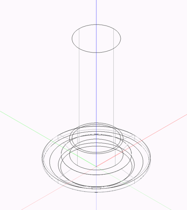
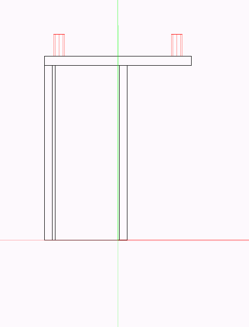
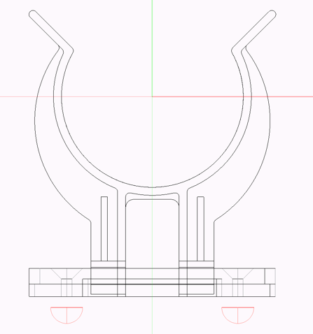
In front view, the x-axis runs centered through the CNC machinings. In the top view the z-axis is the centre of the tube. Note:- The space for the plinth panel spring under the cabinet Bottom is indicated as a tech value (plinthreduction).

Easily create new legs or handles
With the function »interiorcad > Fittings > Assign Fitting Type« you can easily create new legs or handles. You can either create a fitting from the selected objects or from all symbols.
To use this function, it is necessary, that the selection or the symbols contain machinings (e.g. a drilling in the correct direction)
- Select any objects / symbols including machining.
- Select »interiorcad > Fittings > Assign Fitting Type«.
- Select the fitting type. In the input fields, you can also specify the following values for the "interiorcad sales info database": "Description", "Supplier", "Order ID" and "Price".

Clicking the „Assign“ button will assign the „interiorcad sales info database“ to the corresponding objects.
With the option „All symbols“ you can also make all symbols of a document handles/feet.
Creating Grids in Library
To create a new grid, duplicate an existing grid in the »Resource Manager« by right-clicking the Grid and choosing «Duplicate».

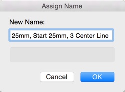
Enter a new name an click on «OK».
Then right-click the new symbol, choose Edit and select the «3D Component» of the new symbol.
You just have to adapt the data (Start, End, grid-width and centered in X and Y). After saving the document, the data is automatically picked up by the connector tools.
Grid Object
The Grid-Object draw lines along the X-Axis and the Y-Axis. The Grid-Object has for each axis following settings:
Grid X or Y: This option defines if the grid has to be drawn or not on the corresponding axis.
Start at Center: This option defines if the grid has to be drawn starting from the center or from the edge.
Start Distance: This option defines the first distance of the grid relativ to the reference center or edge (see option Start at Center).
Min. End Distance: This option defines the at least distance at the end.
Width: This option defines the grid width after the start distance.
Mirrored grids are not supported.
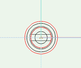
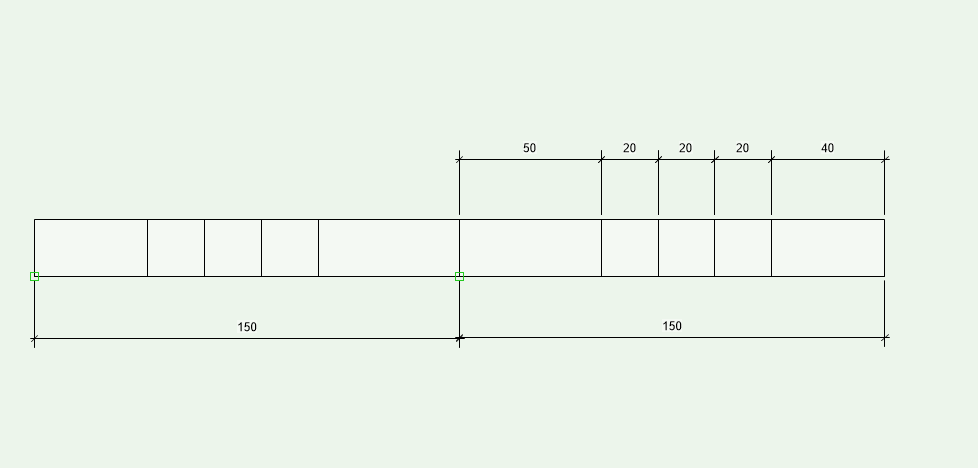
Example 1 (Start at Center: Yes, Start Distance: 50, Min. End Distance: 30, Width: 20))
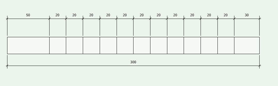
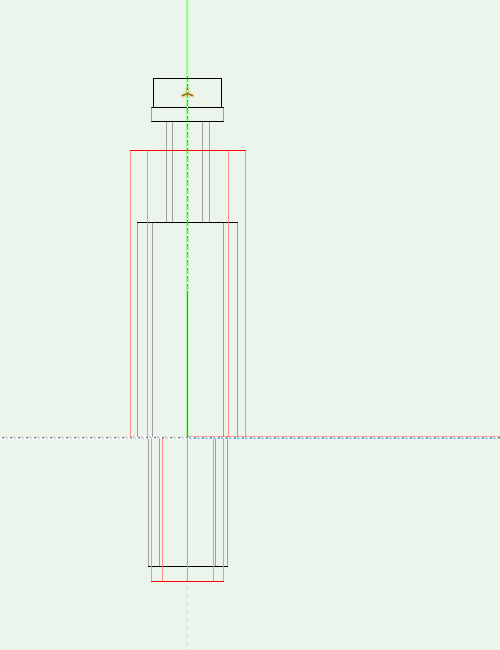
Example 2 (Start at Center: No, Start Distance: 50, Min. End Distance: 30, Width: 20)
The distance at the end is at least 30 in both examples (picture 1 and picture 2). In picture 1 is the end distance 40 and in picture 2 30.
Creation of Grids (for fitting positioning) now has an «Advanced» - option, which, similar to classic cabinet connector distribution, takes a string for specification.
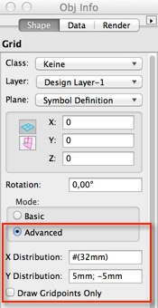
Grid Definition String options currently supported:
Fixed value from beginning and end (of the custom part) with positive/negative values
«80 -80» creates a grid with one line 80 from from beginning and one line 80 from end of the custom part
Centered between two fixed lines or beginning and end with «#»
«#» creates one line centered one the custom part
«80 mm;#;#;-80 mm» creates a line 80 mm from the beginning, 80 mm from end, between two lines evenly distributed
Conditional lines with «position(>SizeOfGrid/CustomPart)»
«#(>300mm)» creates a centered line if custom part is at least 300mm in size
«80mm;#;#(>500mm);-80mm» creates three lines if custom part is smaller than 500mm. Size 500+ creates four lines
Cluster-lines/drillings with «position(GridWith*DrillingCount)»
«80mm (32mm*5)» creates a line at 80mm, 112 mm, 144 mm, 176 mm and 208mm
«-80mm(-32mm*5)» creates 5 lines with 32mm distance, starting 80mm from the end of the custom part
«#(20mm*3)» creates three centered lines with 20mm distance (one before, one centered, one after)
«#(20mm*3>500mm)» creates three centered lines with 20mm distance (one before, one centered, one after) if custom part is larger than 500mm
Grid drillings
«80mm(32mm)» creates lines with 32mm distance from 80mm to end of custom part
«#(32mm)» creates lines with 32mm distance from beginning to end of custom part. One line is exactly in the center
«80mm(32mm);-80mm» or «80mm;(32mm);-80mm» creates lines on 80mm and -80mm from end of custom part and centred lines with 32mm distance between them.
«80mm; (32mm);-80mm!» creates lines with 32mm distance from minimum 80mm to minimum -80mm from end of custom part. The distance between the lines is always 32mm. The distance to the first lines is > 80mm on both sides.
The values should be separated with «;» and should have a measuring unit, for example 80mm to prevent showing the grid in the unit used in your document. By changing the signs (example -60mm; #; #; 80mm), the rasters are applied from top to bottom and from right to left.
Create a new profile
You can create 2D-profiles individually in the "Top/Plan" view. Profiles are defined by Vectorworks symbols that contain the 2D section of the profile.
This profile can be used with the "Profile 3D" tool to edit parts. It can also be imported during configuration in the “Cabinet 3D” generator, e.g. during frame editing. The profile machining of a workpiece is then completed later on the machine with a suitable profile cutter.
Draw the profile with a tool of your choice. The zero point of your drawn profile corresponds to the point at which the upper right edge of the part would abut. In the illustration it is represented by the coordinate system.

The part that is milled from the component is the part of the polygon that is located in the lower left quadrant of the drawn coordinate system.
When drawing the profile, make sure to always draw at least 1 millimeter projection to the right and above the zero point. This ensures that the component is milled off without leaving any residue. In the example illustration, this area is to the right and above the third quadrant of the coordinate system.
You can also add a groove (figure below) or rebate to the profile, for example. Make sure that your profile again overlaps at least 1 millimeter on the corresponding side.

Now create the profile as a symbol with "Modify > Create Symbol…". Assign a name and select "Plan Projection Center" under "Insertion point". You can select your created profile for editing via the "Profile 3D Tool Settings".