Create Part Layout
Create measured part layouts of cabinets and custom parts
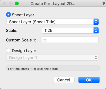
Mark cabinets and custom parts and select Interiorcad > Create Part Layout command to produce dimensioned 2D workshop drawings and choose whether to insert the Part Layout in the 'Sheet' or 'Design' Layer. In 'Sheet' Layer, scale can be specified. However, In 'Design' Layer the scale is automatically provided. Finally, on selecting OK, an intelligent object is inserted.
Changes in the Object Info Palette are automatically applied. To adjust the part layout to a change in your furniture, select «Update».
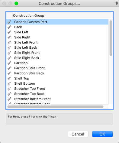
By clicking on Construction Groups you can filter the outputs of the group. Click on the checkbox in front of the group output to show or hide it.
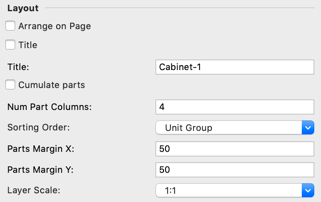
Layout section
In Layout section a title for the Part Layout can be entered (optional only). In addition, the number of columns can be adjusted to the page size or manually selected. In addition, distance between parts and the sorting order can be set. If the Part Layout is produced in 'Sheet' Layer, the scale can be adjusted here.
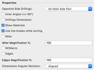
Properties section
In the Properties section, Drillings on opposite sides can be controlled. Information about the inner angle, the location of the drillings and the material names can be viewed or suppressed. When sorting by 'Unit Group', Line breaks can be switched on. Likewise, miters, edges and information about NC macros can be switched on or suppressed. So that miters and edges can be displayed at all, they are displayed enlarged by x%. The Dimensions of Angular Sections can be 'Aligned' or 'Rectangular'
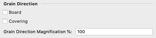
Grain Direction section
The Grain Direction section, the grain direction be shown for board and/or covering. The grain magnification may also be toggled.
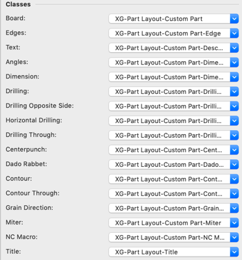
Classes section
In the Classes section, the classes that control output can be amended.